

FAA regulation 14 CFR 25.581 is an important lightning protection regulation for part 25 aircraft. In this article, we’ll discuss in-depth (in both video and written form) the five steps involved in compliant designs.
Watch Our Video Tutorial Below on FAA 14 CFR 25.581
Watch the video below to see the full presentation, or read on to get Allen Hall’s presentation on FAA 14 CFR 25.581 in written form.
Jump to Any Section
- Watch Our Video Tutorial Below on FAA 14 CFR 25.581
- FAA Warning: Must Prevent Catastrophic Effects of Lightning
- SAE Documents for Compliance
- The Five Steps to Compliance with 25.581
- Step 1: Defining Aircraft Lightning Strike Zones
- Step 2: Lightning Environment
- Step 3: Lightning Hazard Assessment
- Step 4: Design Protection for Metallic Components
- Step 5: Verify Compliance with FAA Lightning Regulations
- Questions on Your Radome Design or FAA Regulations?
FAA Warning: Must Prevent Catastrophic Effects of Lightning
The picture below is from a lightning-related crash from 2003. Lightning struck the empennage of this small aircraft, resulting in flight control issues. Yes, they made it to the runway but still had a very serious accident and complete loss of the aircraft. This was a dangerous situation.
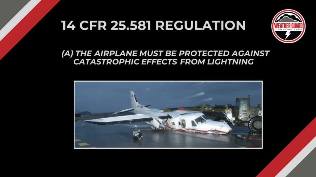
Lightning strike damage that results in this sort of catastrophic event is rare, but still a possibility anytime a plane takes flight. We, as design engineers, need to keep compliance top-of-mind and always remain vigilant on safety.
The Russian AeroFlot Flight 1492 crashed after a lightning strike in 2019. We talked about this crash on Struck, our audio and video podcast as an example of an extremely modern aircraft succumbing to lightning.
A closer look at 25.581 regulation:
(a) The airplane must be protected against catastrophic effects from lightning.
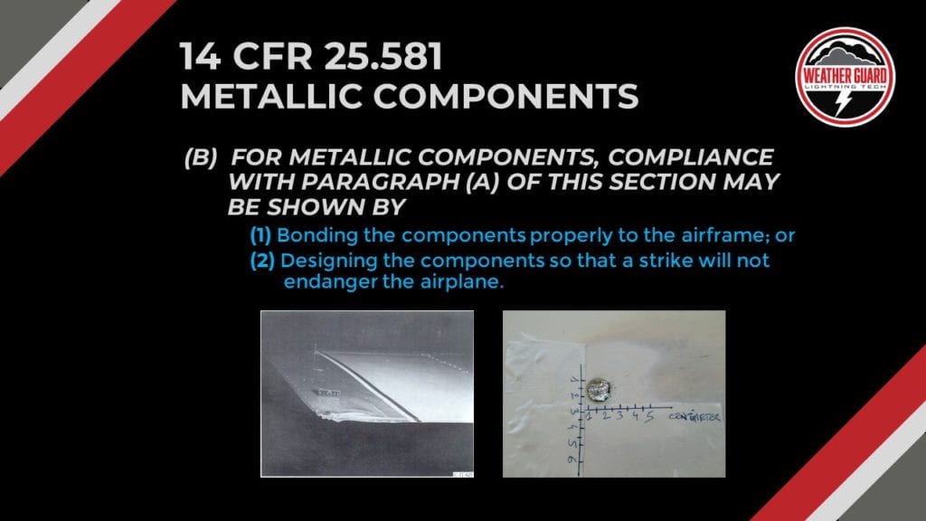
(b) For metallic components, compliance with paragraph (a) of this section may be shown by –
(1) Bonding the components properly to the airframe; or
(2) Designing the components so that a strike will not endanger the airplane.
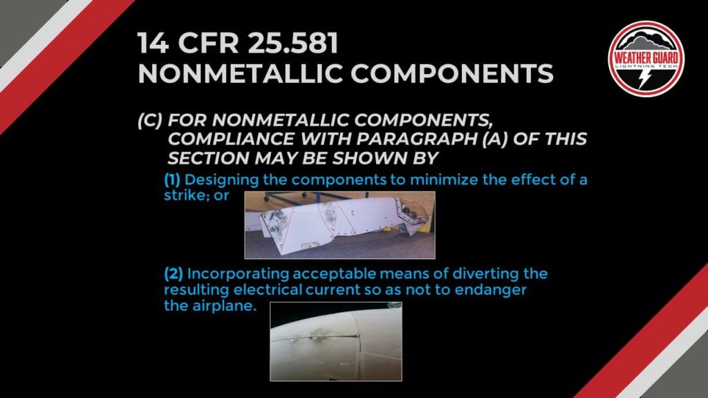
(c) For nonmetallic components, compliance with paragraph (a) of this section may be shown by –
(1) Designing the components to minimize the effect of a strike; or
(2) Incorporating acceptable means of diverting the resulting electrical current so as not to endanger the airplane.
Let’s talk through two examples:
First: a strike to a King Air wing, which wrinkled up the wing tip. The strike actually wrinkled parts of the wing and the fuselage so it’s a pretty strong lightning strike.
A more common case here is a lightning strike to a rivet on an airplane where it just melts the head of the rivet.
Let’s go to part three of the regulation non-metallic components, C for non metallic components.
Compliance with paragraph a) of this section may be shown by minimizing the effect of a strike. And in this particular case, we show a carbon fiber wingtip that has incorporated metal foil on the outside to minimize the effects of a strike. That’s a very common design technique, putting some conductivity on the outside of a piece of carbon fiber structure to minimize the effects.
Part two of this regulation is incorporating accessible means of diverting the resulting electrical current so it won’t endanger the airplane.
Now in this particular case, what we see is a nose radome for an Airbus airplane. Nose radomes are typically made out of fiberglass or Kevlar, they’re non-conductive. And so in this particular case, what has been done, there’s a copper strip that’s applied to the outside of the radome to divert the current safely back to the airframe.
So, in both cases and minimizing the effect of a strike or in diverting it, when you get to talk about non metallic structure, components, those are really the two compliance methods that the regulation points out. So those are the three parts to the regulation.
SAE Documents for Compliance
Now let’s look at the documents you’ll need. There are four documents from the SAE that are essential:
- ARP5577 – Aircraft Lightning Direct Effects Certification
- ARP 5414 Aircraft Lightning Zone
- ARP 5412 Aircraft Lightning Environment and Related Test Waveforms
- ARP 5416 Aircraft Lightning Test Methods
You can find these documents at www.sae.org online.
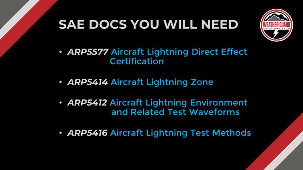
These SAE ARP documents are not free, but make the investment, as you’re going to need all four of those documents for compliance with 25.581.
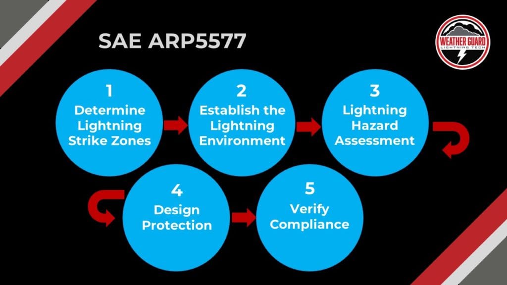
The Five Steps to Compliance with 25.581
These are described in general in ARP5577.
Step one is establishing proper lightning zoning.
But, let’s simplify them a little bit because ARP5577 can get a little bit complicated. This document helps us determine the lightning strike zones for the aircraft.
Next, we need to figure out where lightning is likely to attach to the airplane.
Step two is establishing a lightning environment.
So if lightning strikes a wingtip, how much energy is going to be applied to that?
Three, we’ll perform a lightning hazard assessment.
We need to determine what the likely outcome of a lightning strike to a particular component to make sure that we understand what the implications are for the safety of the aircraft for we need to design protection. Figuring out which parts of the airplane may be vulnerable is crucial.
Four, we need to apply some sort of protection to the design of the part, and then the final step is verification.
Step 1: Defining Aircraft Lightning Strike Zones
So step one of the five step process is lightning strike zones and defining what the lightning strike zones are for the aircraft. The place you need to go is ARP5414 – that’s going to define the aircraft zones for most aircraft. Now, just to simplify it a little bit, I broke it into the three basic zones:
- Lightning zone one
- Lightning zone two
- Lightning zone three.
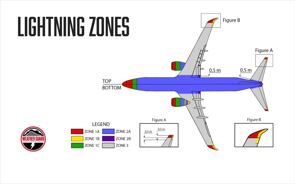
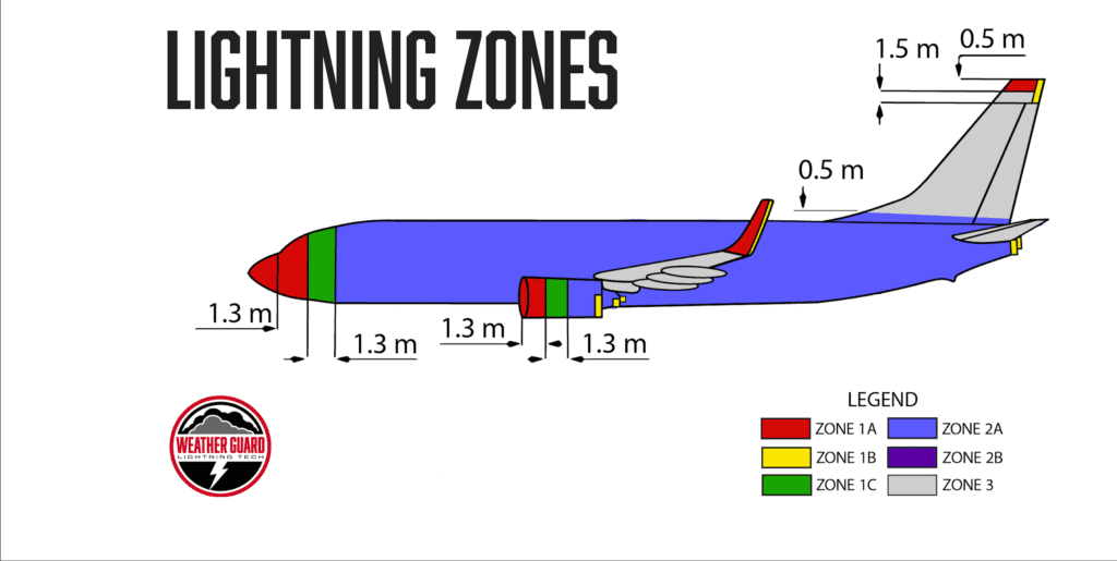
Zone 1: the extremities, the nose, the wing tips, the empennage tips.
Zone 2 tends to be the main body of the fuselage, parts of the wing, and then the empennage or tail.
Zone 3 is everywhere else, essentially–Big portions of the wing are in lightning zone 3; lightning zone 3 is a place where lightning is not likely to attach.
Zone 1 is where lightning is most likely going to initially attach. Zone 2 are the areas where lightning has a low likelihood of initial attachment, but lightning may still attach during the lightning event.
So, a strike to the nose as the aircraft moves forward–that strike will move down the fuselage. This means that the initial strike zone may have been the nose–which had been zone 1–but then the fuselage is in lightning zone 2. This shows how it can change because of the plane’s movement.
Step 2: Lightning Environment
Step two is defining the lightning environment, and this document is ARP 5412. 5412 associates the lightning zones with particular amounts of voltages and currents. Just to keep it simple here, zone 1 can experience up to 200,000 amps. Lightning zone 2 can experience 100,000 amps.
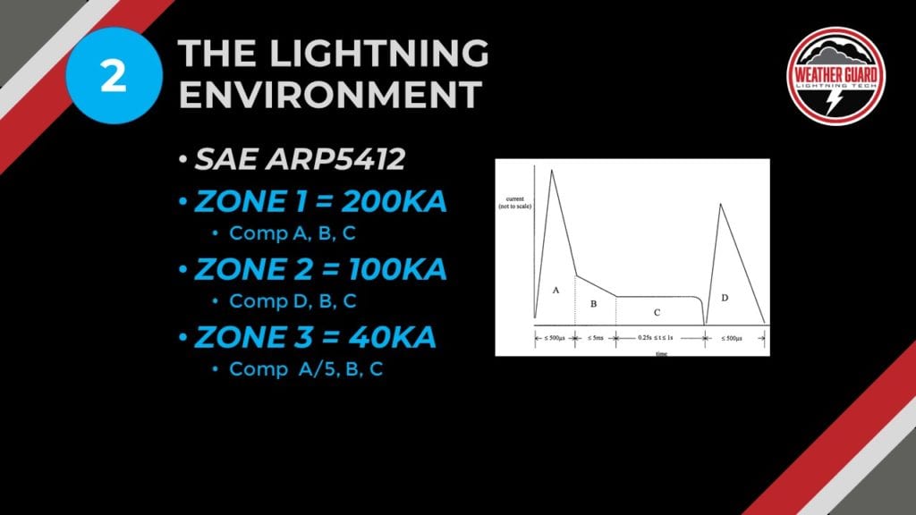
Unique and novel features in lightning zone 3 are that the SAE group recommends testing it to 40,000 amps.
Here’s a quick recap:
- Zone 1 is 200,000 amps
- Zone 2 is 100,000 amps
- Zone 3 is 40,000 amps
Step 3: Lightning Hazard Assessment
The third step is the lightning hazard assessment.
This is where you want to spend most of your time. You’ll want to do an evaluation of the potential lightning damage, and to do this you’ll look at all aircraft structures, systems, and components.
You will want to determine if there could be some sort of catastrophic effect, a failure or a malfunction, and whether it could happen immediately or after some delay.
For example, a strike to a wing tip could cause a wing tip to deform to the point where it bumps into an aileron and you may not notice it until later into flight.
Or, perhaps a strike to a flap; you won’t deploy the flaps until later in the flight, so you may not even know that the flap has been damaged, as indication would not be immediate. The lightning effect may be noticed further down the flight profile.
We’ll talk about some other areas we need to look at, but first let’s focus on primary structure for those things. If the primary structure took substantial lightning damage, it could cause the loss of the aircraft.
The two documents we would look at (which are free) are:
- 14 CFR 25.571
- the advisory circular that goes along with it: AC 25.571-C
These two documents look at damage tolerance and fatigue evaluation. So you want to do a little research and talk to your structures person. If you’re not a structured person, talk to a structures person about evaluating those structures.
And then you want to look at structural components. Now that could be faster at a major structural joints like a wing spar or a vertical stabilizer spar.
You will need to look at control surfaces, push rods, cables, actuator hinges, bond jumpers. These are things that bring structures together from an assembly, and then externally mount components like antennas or radomes. If an antenna exploded from a lightning event, does it get sucked into an engine? Or, do you have a radome that departs and hits the vertical stabilizer?
It’s very important to determine ahead of time how you want to protect these items. Also, an engineer needs to look at the loss of a system function, particularly mechanical systems.
The simple case in point is an engine cowling that is protecting a FADEC, a full authority digital electronic control for an engine. If the cowling gets hit and the cowling comes apart, does that expose the underlying FADEC to things that it wouldn’t normally see?
Then, looking at primary power – does the strike take out primary power? For example, a strike to a light on a wingtip takes out the aircraft power or a strike somewhere to a hydraulic tube that may be exposed on the trailing edge of an elevator. Does that cause you problems later on?
Now the evaluation you’re going to do here is based on AC 25.1309-1A. You won’t do a 1309 analysis for lightning, but the process is similar.
It’s common to hear engineers talk about doing a 1309 approach on lightning protection. What we’re saying is we’re going to follow the same guidelines in the guidance and how we think about what systems may be affected. And, we’ll look into what the consequences of damage or fear or failure of a component will have on the rest of the aircraft, on the safety of the aircraft. It’s important to try to classify it and create a lightning safety classification system.
Step 4: Design Protection for Metallic Components
Step four is designing protection for metallic components. So on a metal part, the question is: what are we looking at in terms of a design protection? We want to know the type of metal–aluminum, steel or titanium. All three have different resistances and respond differently to lightning energy.
We also need to consider the thickness and the cross sectional area: is the piece thick enough to handle the lightning energy?
It’s also important to consider how it’s attached. If there are two metal pieces and both are stuck together…are they riveted? Or, are they screwed together, bolted, welded or adhesively bonded together? Bonding makes a big difference in terms of what the possible damage would be to those parts.
We also need to look at coatings and electrical bonding – they kind of go together. Are the parts alodined between them, so there’s a conductive coating between them? Or is the metal anodized or painted where there’s a non-conductive coating between them?
Non-conductive coatings tend to do more damage to a component during a lightening event because there’s not a dedicated path for lightning to travel. So lightning makes its own path and when it does, it causes a lot of extra damage.
And then on the non-metallic components, we’re looking at similar things. What is the material? Is it carbon fiber? Fiberglass? How thick is it? Is it a 787 wing section or is it a, a much lighter cross sectional area that tend to be on a fairing where they tend to be very, very thin.
Metal foils – a lot of times metal foils are being used to protect composite structures, be it fiberglass or carbon fiber. Typical things were copper, bronze, aluminum, or even silver coatings, paint coatings – we’ve seen a lot more of that recently.
If you’re going to divert lightening energy – StrikeTape lightning diverters is a very common way to do that. And then we also want to look at how those composite parts are attached to one another. A lot of times it’s by a non-conductive adhesive or sometimes it’s some sort of screw or bolt or fastener that holds those parts together.

You’ll get a sense of what the likely damages will be and what’s at risk. If you burn out some fasteners, do you then not have enough structure to carry the load? These are things you need to think about when you’re building carbon fiber or fiberglass parts.
Then, look at electrical bonding. There can be electrical bonding issues with non-conductive or highly resistive things like carbon fiber. You still want to make connections where you can to safely carry the lightning current.
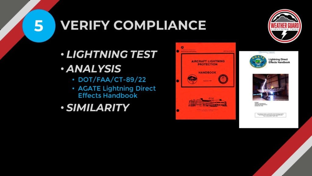
Step 5: Verify Compliance with FAA Lightning Regulations
Step five–which is probably the most expensive step of all–is verifying compliance. This is primarily done with lightning testing. And the best thing to do that (depending on where the customer is) is to just check Google and see what’s close.
Ideally, you’d take trip to a lightning lab that’s competent and relatively close to your facility. This saves you a bunch of time. Building a relationship with them is a great thing.
There are really two documents you can use and the FAA would allow you to use:
- DOT/ FAA/CT-89/22
- This is the aircraft lightning protection handbook.
- AGATE Lightning Direct Effects Handbook
- Ed Rupke put together from Lightning Technologies. That is a great handbook in the sense that Ed did a lot of testing on carbon fiber and fiberglass parts, protected with a variety of very common lightning protection foils.
The last thing to consider is similarity.
The bigger aircraft companies–like an Embraer or an Airbus or Boeing, even Cessna, Cirrus, where they have a lot of data already, would use similarity because they have test data as a foundation. Similarity gets used a lot for existing designs and parts that have been transferred from one aircraft model to another.
Questions on Your Radome Design or FAA Regulations?
We hope this discussion of the five steps in radome lightning protection has been helpful. It’s definitely a bit complicated, but totally manageable with attention to detail and the right guidance.
If you need help with your radome design, give us a call or send us an email today.